How to Create a Simple ERD in SSMS
In this post you'll learn:
- how to create a new Entity Relationship Diagram in SQL Server Management Studio
- how to add tables and columns
- how to relate two tables together using a foreign key
Let's get started.

Create a New ERD
SSMS (SQL Server Management Studio) includes the ability to create Entity Relationship Diagrams.
You can create them by importing tables from your database or creating one from a blank page. In this guide, we'll look at creating a diagram from a blank page.
To do this, start by connecting to a database.
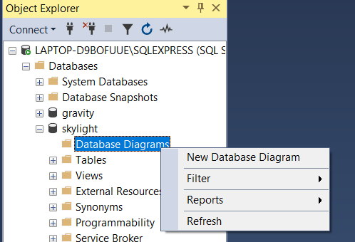
Expand the Databases folder, then your database.
Right-click on the Database Diagrams folder and select New Database Diagram.
If this is the first time you're doing this, you may get the following message:
"This database does not have one or more of the support objects required to use database diagramming. Do you wish to create them?"
Click Yes on this prompt.
Add a Table
Now that you have an empty diagram, the next step is to add a table.
Right-click on the diagram and select New Table.
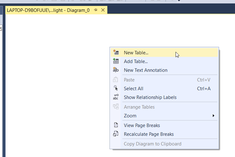
If you select Add Table, you'll be prompted to select an existing table from the database. In this guide we're focusing on new tables, so we want to select New Table.
A window appears for you to add a new table.
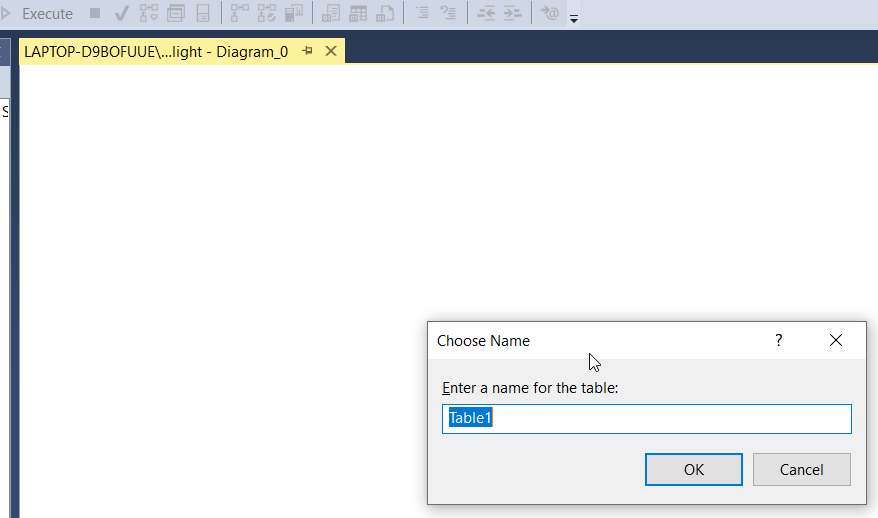
Add a name for the table. In the example above, I've named it car_makes.
You'll see the new table added to the diagram.
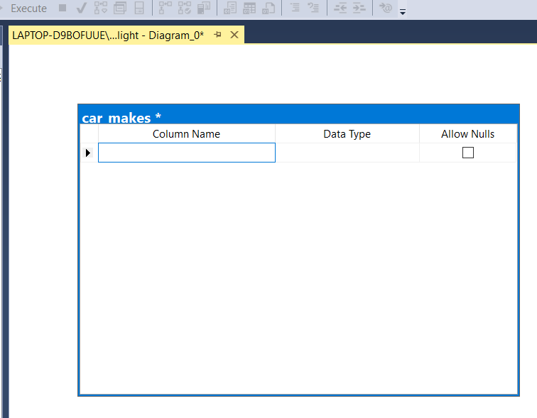
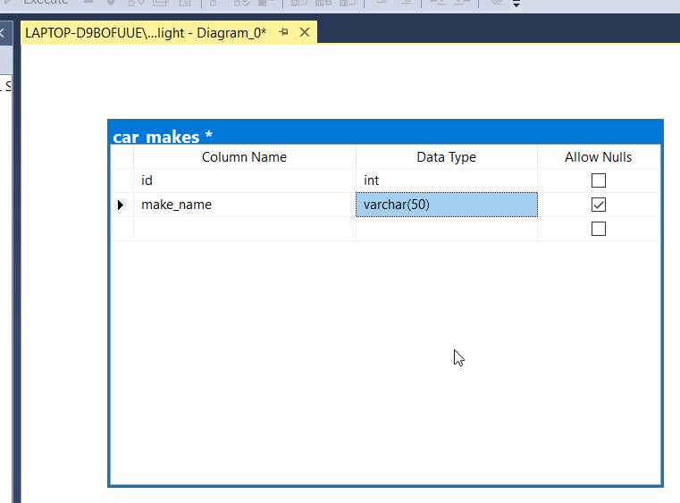
Now let's enter some columns. Enter the name of a column you want to add, and select the data type.
In this example, I've added two columns.
If you click outside the table, you'll still see all of the columns.
This may seem like a lot of information to display for a table on the diagram. Fortunately, it's easy to change the view.
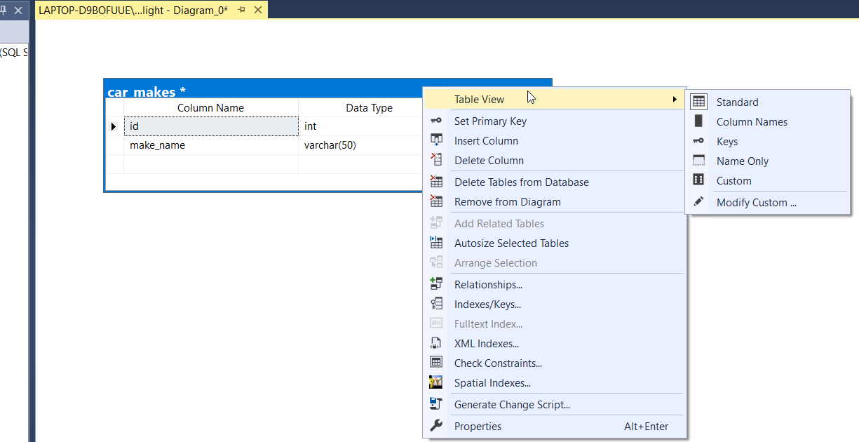
Right-click on the table and select Table View. You'll see a range of different options:
- Standard (the current view)
- Column Names
- Keys
- Name Only
- Custom
Select the view you want to use, or select each of them to see what they look like.
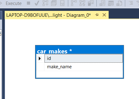
I'll select Column Names to show fewer details but I still want to see the names.
Relate a Second Table
After you add one table, you'll probably want to add a second table and relate it to the first.
To add a second table, you follow the same process as adding the first table: right-click, select New Table, enter a table name, and enter columns.
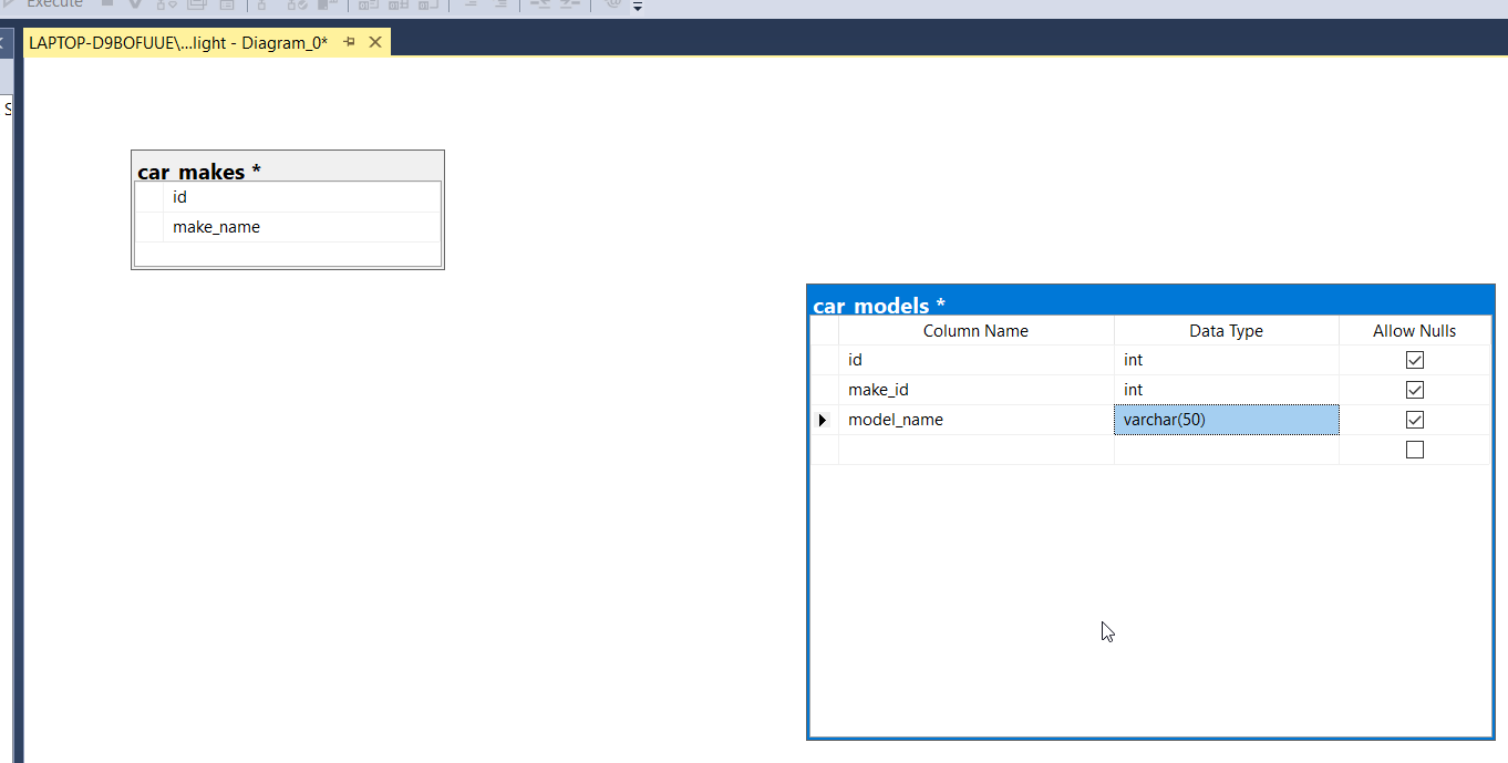
Here's what the diagram may look like with a second table:
We haven't yet specified the primary keys for each table. You can do this by right-clicking on the column inside the table you want to set as the primary key and clicking Set Primary Key.
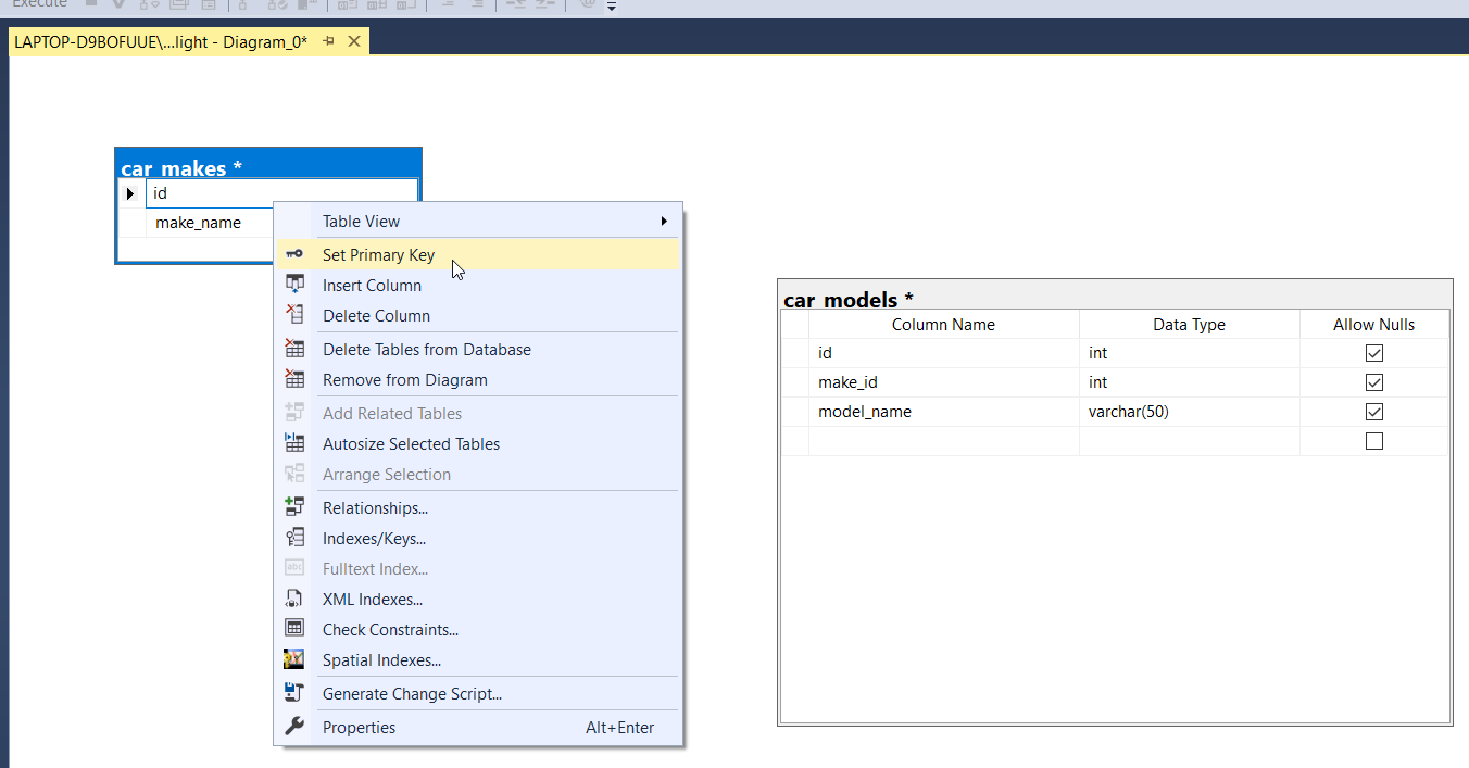
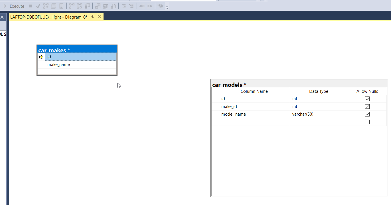
The column will then be marked as the primary key and have a little yellow key icon next to it.
How can you relate the first table to the second table?
You can do this by adding a foreign key constraint to the table.
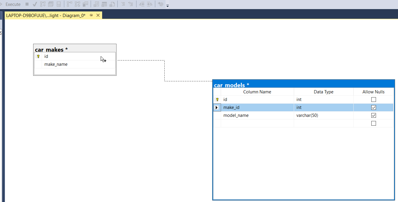
One way to do this is to right-click on a table and select Relationships.
However, I found an easier way to do this is to drag your mouse from the foreign key in one table to the primary key in another table.
When you do this, two new windows appear.
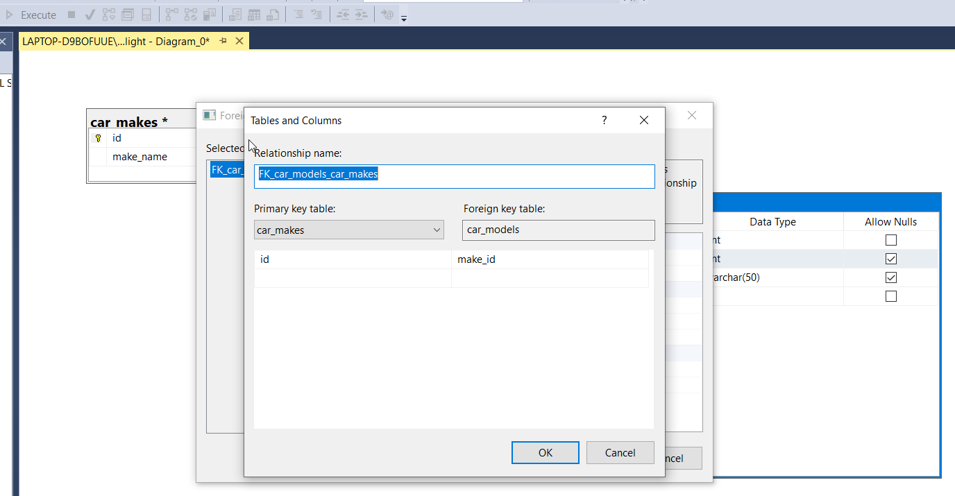
The first window asks you to enter a name for the foreign key constraint. Enter a name.
It will then automatically populate the primary key and foreign key columns, but you can change them if they are incorrect.
Click OK when you are done.
You'll then see the Foreign Key Relationship window, where you can set extra properties for the foreign key.
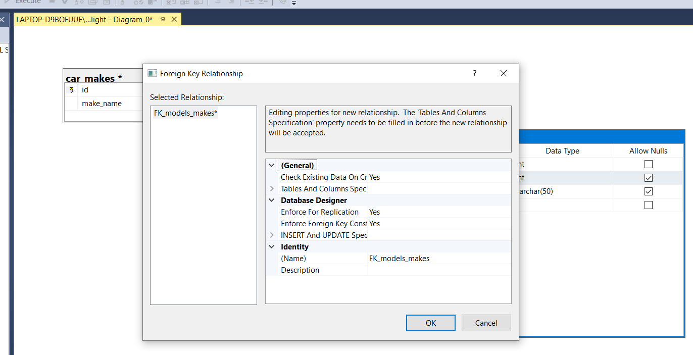
For our purposes, we don't need to change anything here, so click OK.
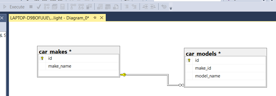
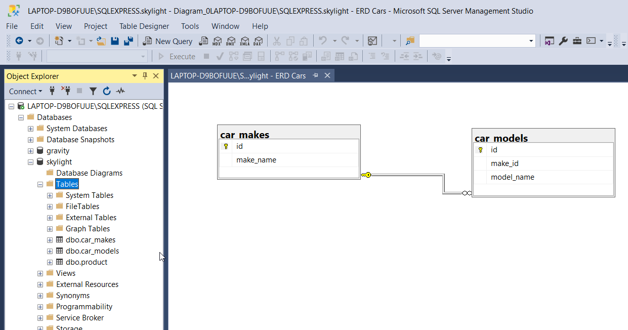
The diagram will be updated with a line between the two tables.
In this example, I've changed the second table to show Column Names only.
Save the ERD File
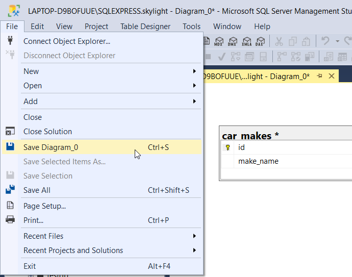
If you want to save your diagram file, you can do that easily.
Save it by clicking on the Save icon, going to File > Save Diagram, or pressing Ctrl + S.
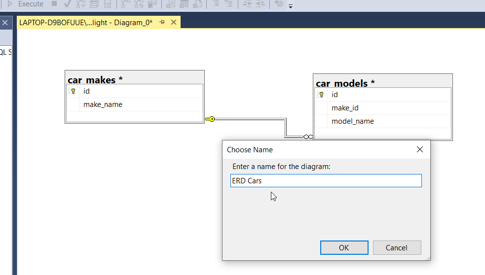
Enter a name for the diagram and click OK.
You're prompted with a message saying that the tables will be saved to the database. This means they will be created in your database as empty tables.
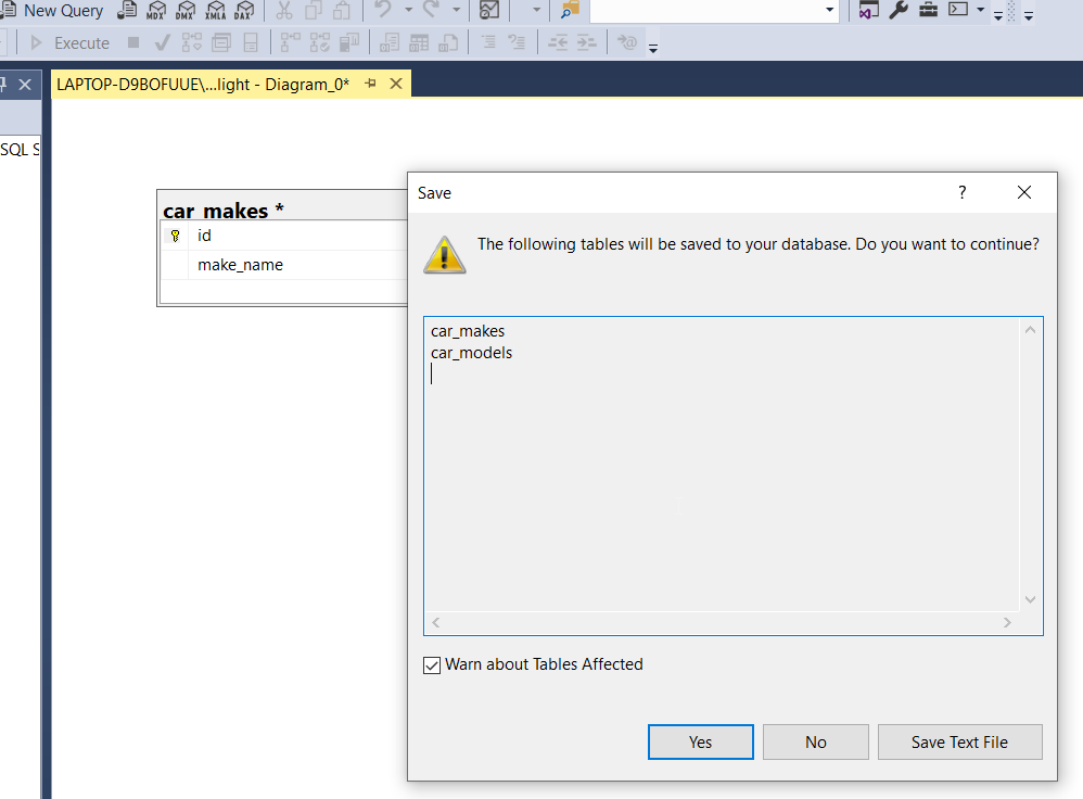
If you want to continue, click Yes.
A few things happen:
- The diagram is saved under the Database Diagrams folder. You may need to refresh the folder to see it.
- The tables are created on the database.
Conclusion
The ERD tool within SSMS is pretty easy to use to create a quick diagram of a database, either from scratch or using the existing database table. There's much more that the tool can do, but this guide has shown you some of the basics.